This is HQ EV CLINIC Lab for EV Research and Development, EVC Academy trainings, franchising and Networking. For service appointement, choose franchise locations. Dismiss
Repair manual price: 1800€ + Tax This operation manual is a proprietary business secret that outlines the successful refurbishment process for DCDC 400V system. By following the provided instruction steps, which include text, images, and videos, you will be fully equipped to repair the DCDC effectively and efficiently in 70% cases
You can charge this service: 1800€ . New OEM DCDC is 7000€ You need 16 labor hours to deploy this repair (Remove / Repair / Assembly)
Common causes:
Factory defect design
Design flaw
Shorted/Bad 12V Battery
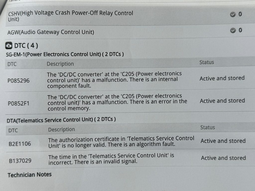
Errors:
P0852F1,
P085249,
P085296,
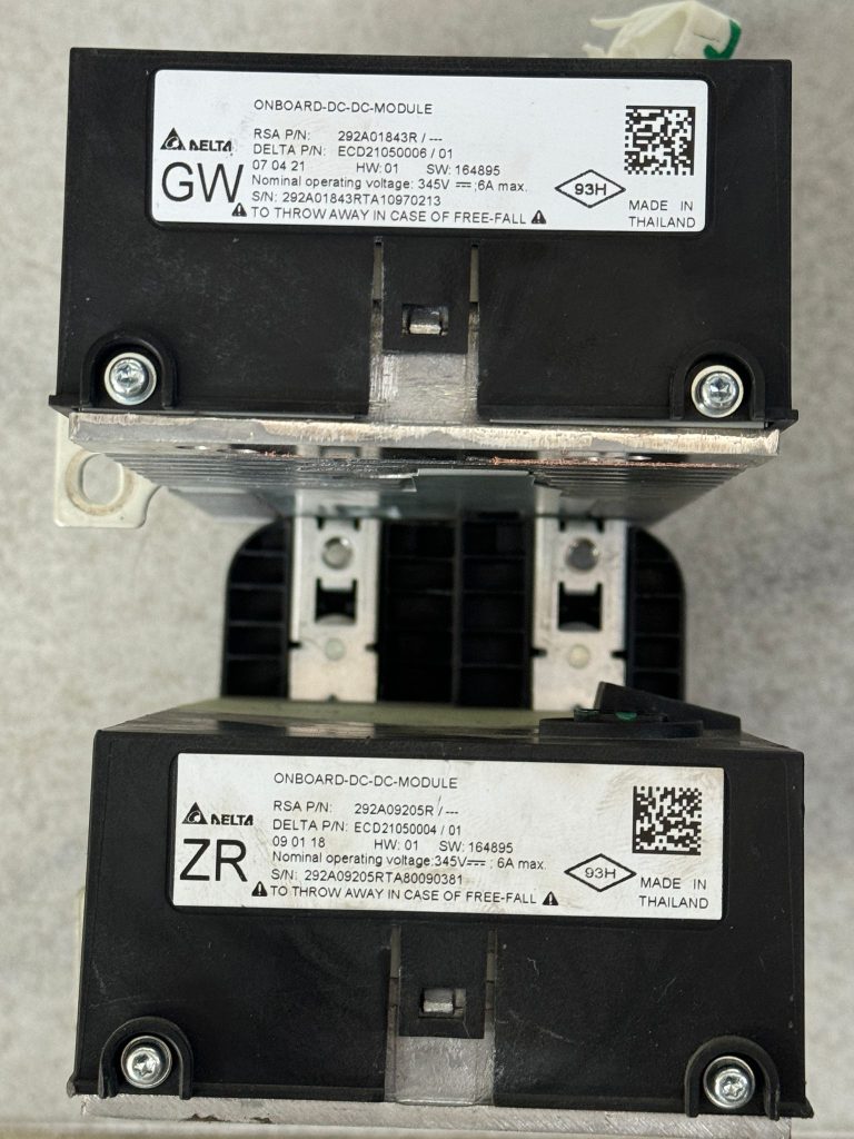
Part numbers:
292A01843R,
292A09205R,
Tools needed (prepare it) :
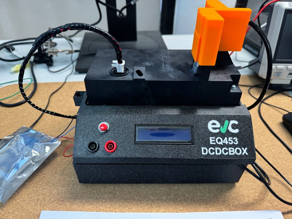
VVDI Prog / Xprog 400V Lab supply ( This one ) Online firmware file editor Weller soldering station 453EQ DCDCBOX ( EV Clinic product )
BEGIN OF REPAIR PROCESS - STEPS
1- First, troubleshoot and confirm that you have encountered errors from the list retrieved via the diagnostic OBD tool. These errors can lead to a permanent lock of the Battery Management System (BMS) if DCDC was on fire or shorted and then BMS will need repair to. This repair covers those DCDC errors and in some cases DCDC is not repairable. However, once unlocked operation manual is not refundable. In 50% cases it is mostly software defect and repair is easy, but in other cases there is HW and SW defect and repair is complex and deep troubleshooting on the bench is needed
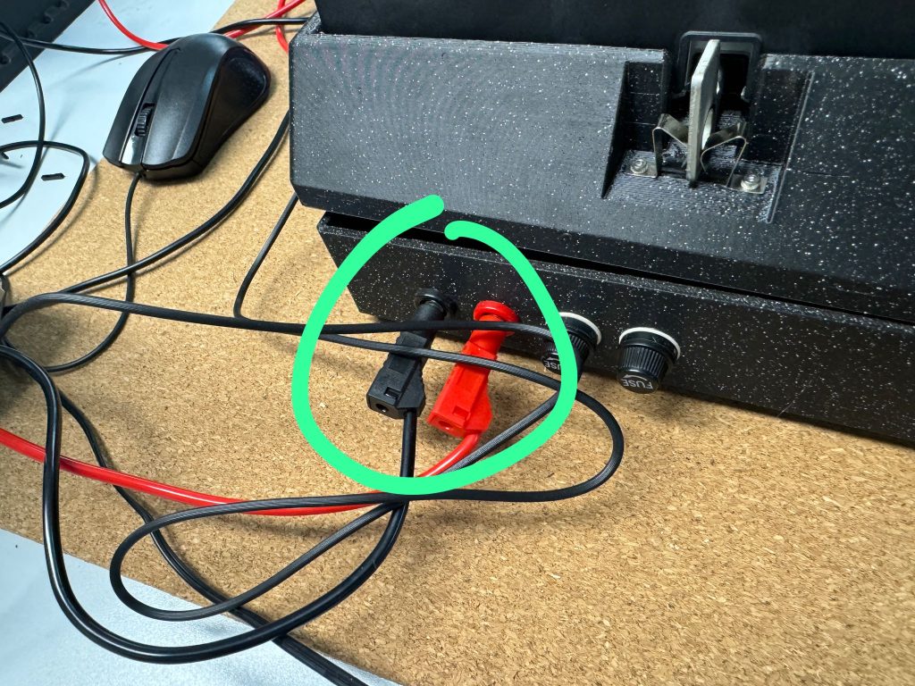
First step is to place DCDC inverter into DCDCBOX device to confirm you got same problem on the bench with 12V battery connected to simulated output
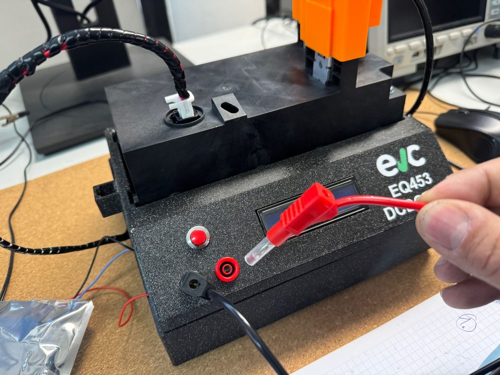
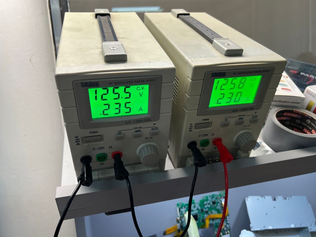
 Now connect 300V-400V powersupply with more than 1 Amp available power to the backside of DCDCBox. (It will work even on lower voltage 240V)
Consumption is 0.24A
In this video is fully displayed how to perform test on repaired and on defect DCDC unit using our DCDCBox device. 300V power supply must be connected to the back of the device, and front is 13.7V input to the Aux battery
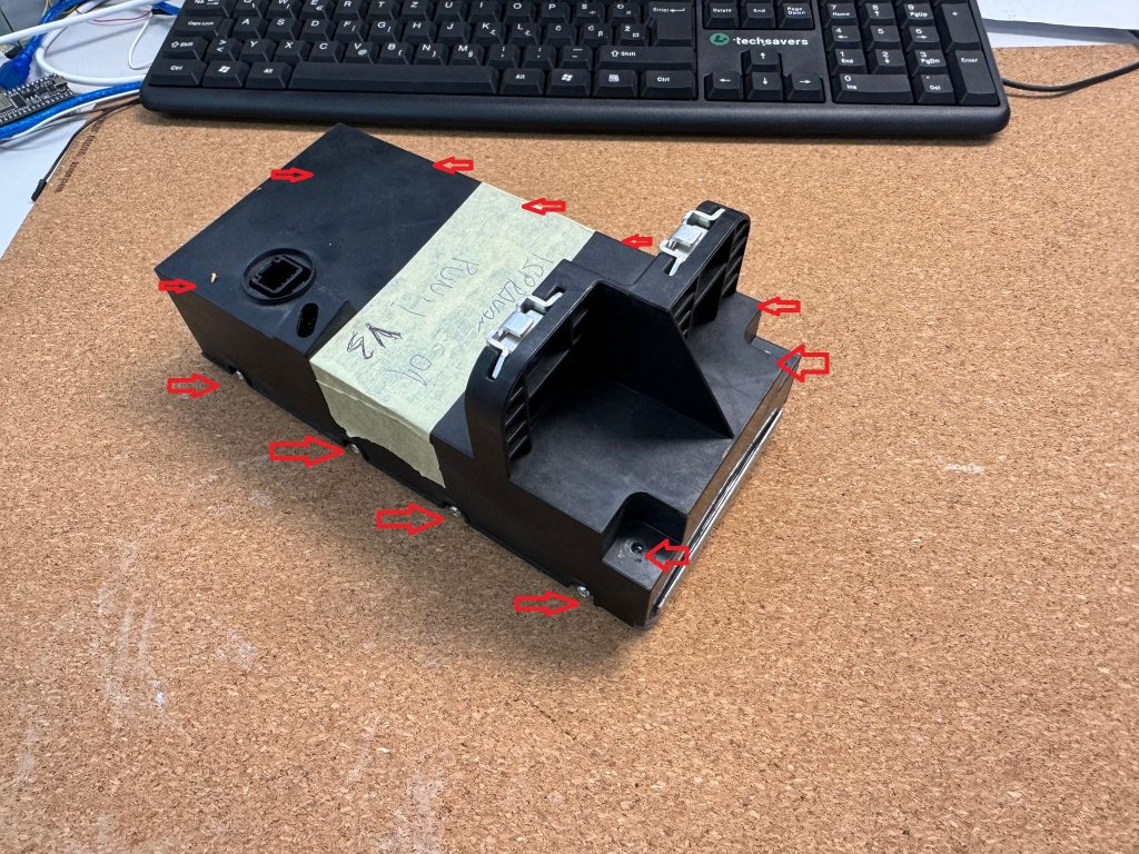
HARDWARE Troubleshooting
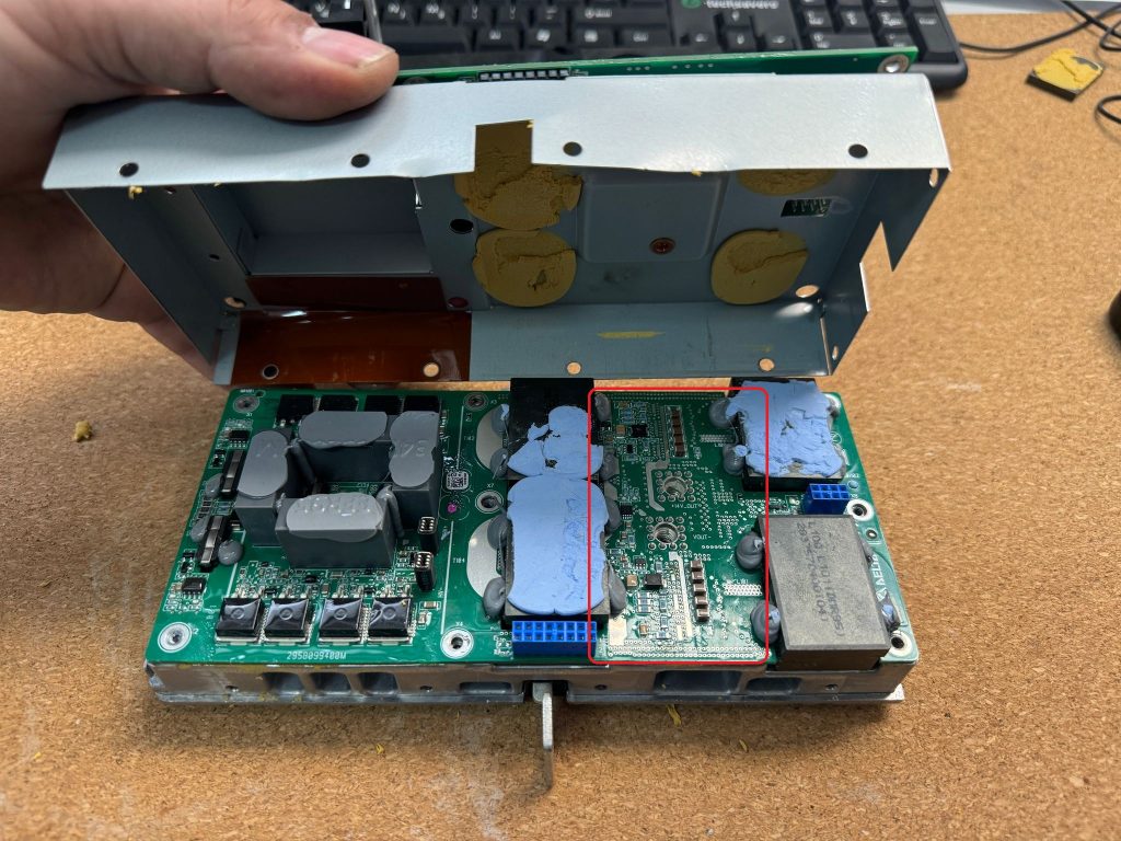
Remove 12 screws marked on picture
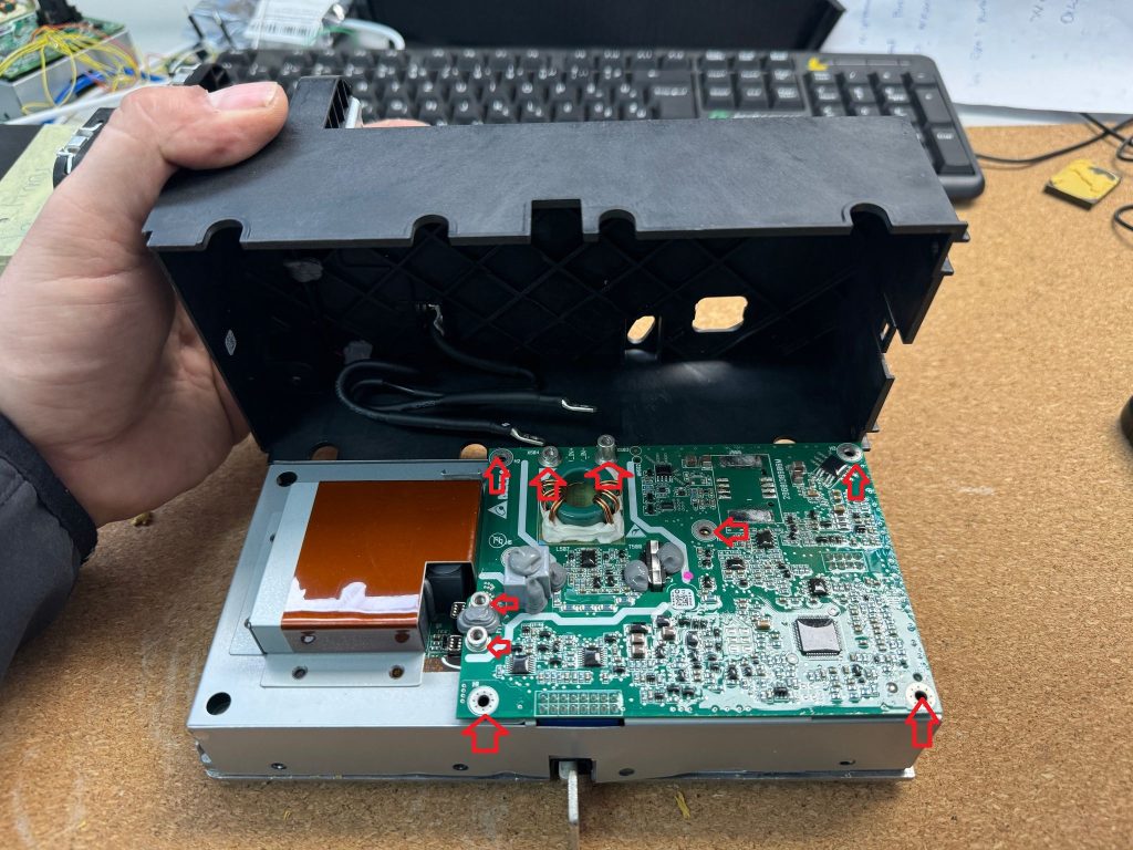
Remove those screws to release upper cover and PCB
This is HV power board with MOSFET components and your zone of interest
Example when it is...
You have reached a restricted content! You must buy this online training operation manual to get access.
Important for ALL customers! 🚗⚡
Our lab is located on a secured site with access control and closed gates, spontaneous visits are not possible!
Due to high demand and our limited capacity, we may not be able to respond to your requests immediately. Delays of up to 2 weeks are possible due to multiple employees being sick and a shortage of workforce.
📅 Please schedule an appointment in advance via email so we can register your access. Visits without invitation is forbiden.