Repair manual price: 1400€ + Tax BUY REPAIR MANUAL HERE This operation manual is a proprietary business secret that outlines the successful refurbishment process for On Board Charger system without destroying complete unit. By following the provided instruction steps, which include text, images, and videos, you will be fully equipped to repair the OBC effectively and efficiently
Info
You can charge this service: 1500€ You need 8 labor hours to deploy this repair
Info
Common causes:
Normal Tear&Wear every 30000km
Unstable grid voltage
Short circuit in the grid on other device
Overheat due empty and failed HVAC system
Info
Errors:
P0DAA00,
P0D5700 ,
P0D2500
Info
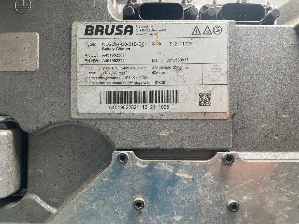
Part numbers:
A4519822221 ,
A4519822821 ,
A4519822621 ,
NLG664,
Info
Tools needed (prepare it) :
Torx T20, T25,
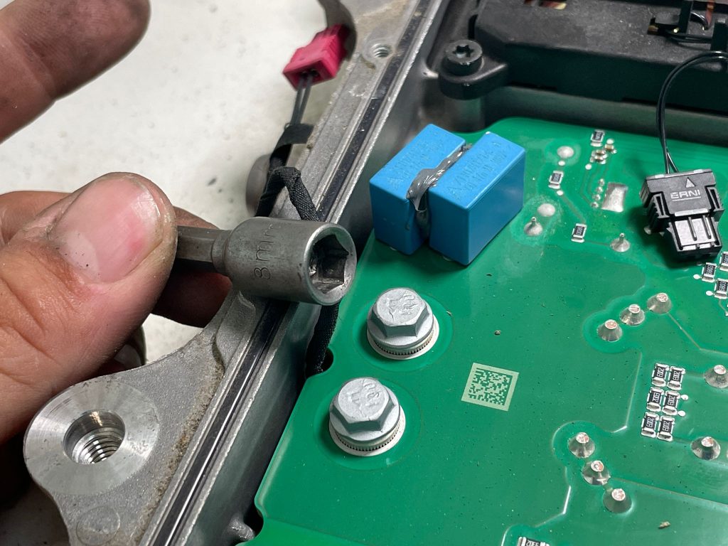
8mm ratchet
Full part list and links (available here)
Soldering iron and hot air gun
Desoldering station (Example SP-1010DR)
Info
Repair operation steps
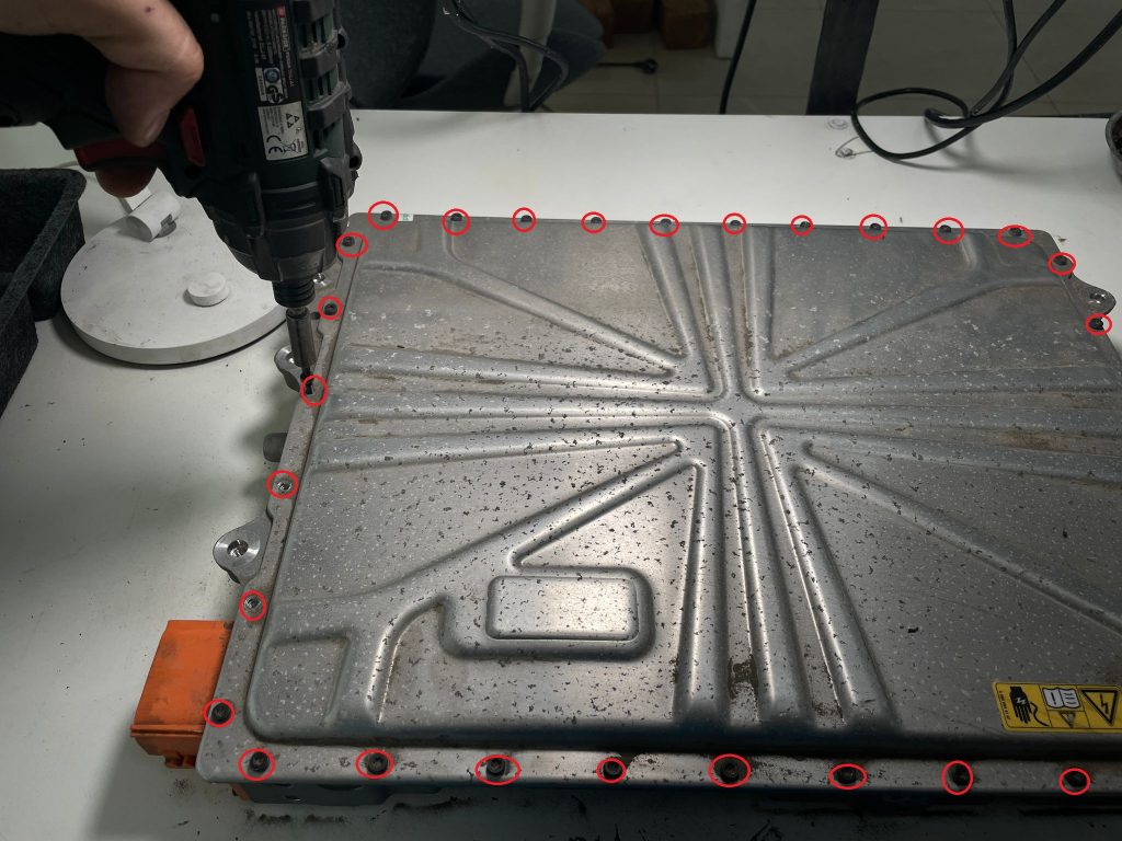
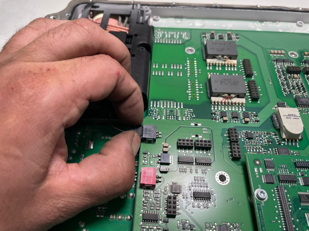
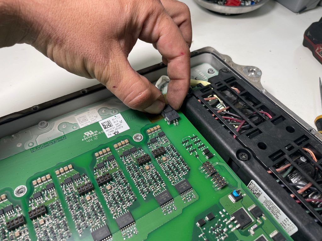
1- Remove all T20 screews from upper cover
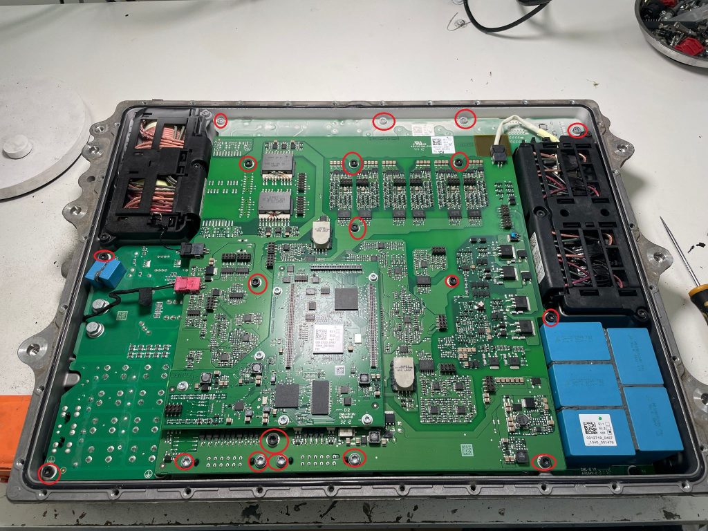
2- Remove cover to reveal PCB board. Remove all T20 Torx bolts from PCB. Dont mix those bolts with bolts from cover. They are not same length
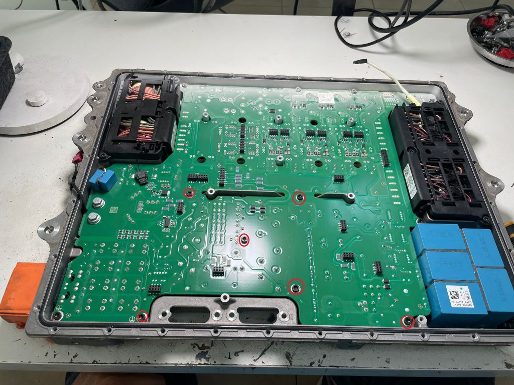
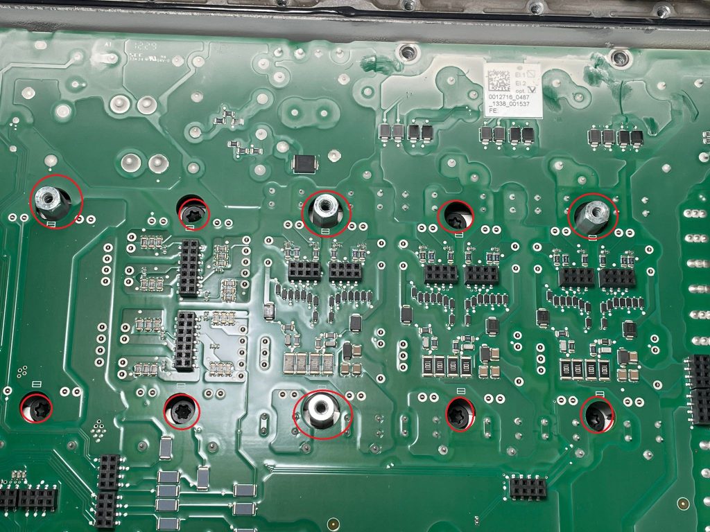
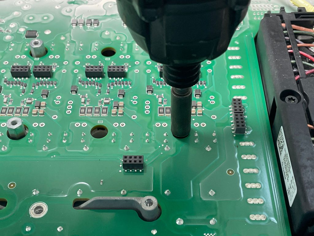
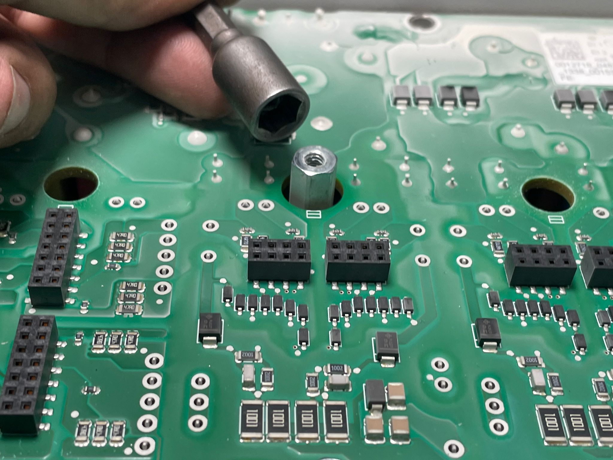
5- Remove T25 torx hidden thru PCB which holds IGBT's, and remove 4 pieces 8mm bolts
X
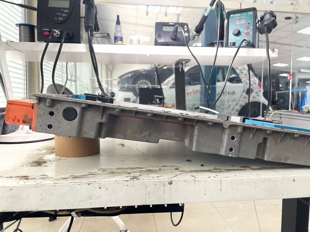
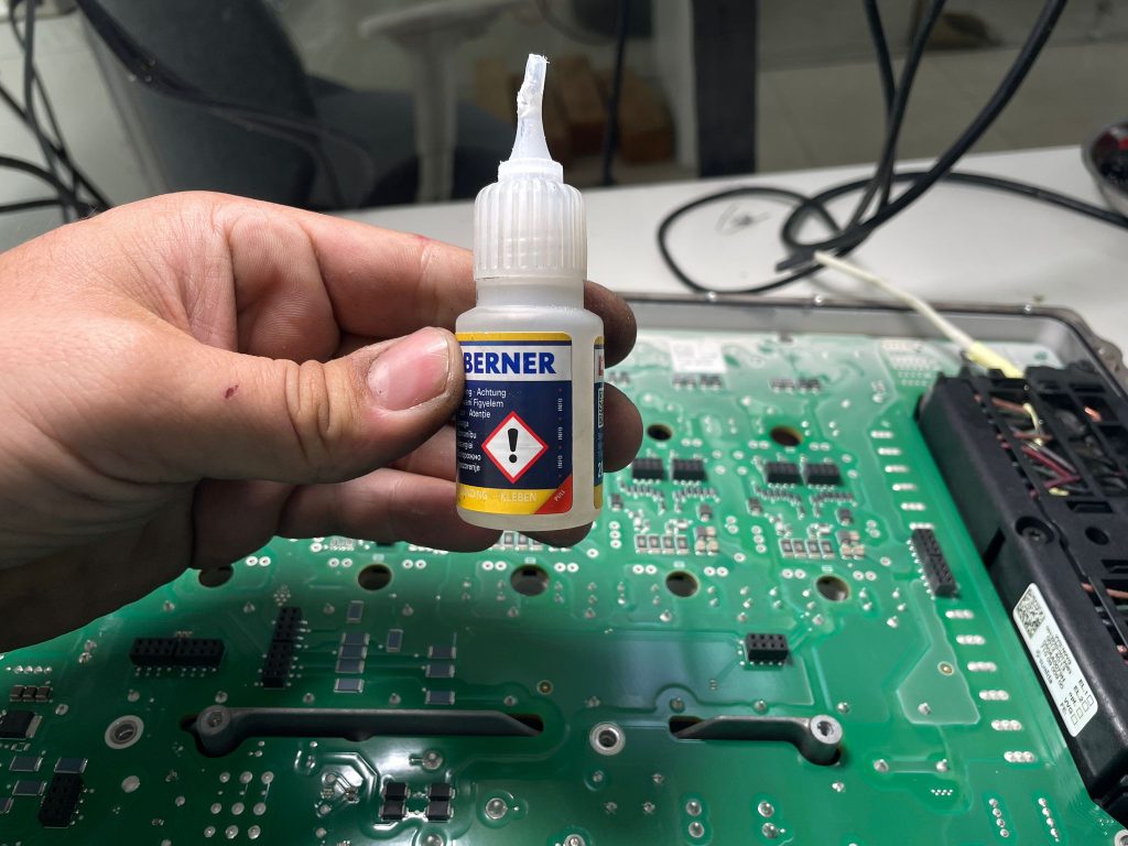
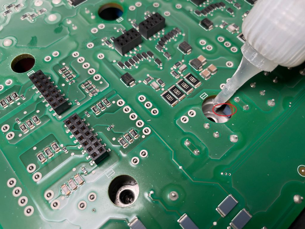
6- Now tilt one side of Brusa charger so we can drop one droplet of glue on each IGBT metal holder. Metal holder moves freely when you try to lift PCB and the that metal will stuck somewhere and it is not possible to return it back into place again. That why we drop glue there, but not on bolt thread inside, we drop glue on one side where metal touches IGBT so it sticks to it while we move PCB around
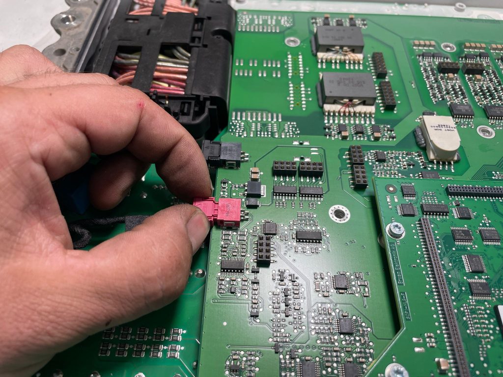
7- Now it is time to lift board. We will show you how to doit in our video here so you dont destroy it. White powder on PCB is...
You have reached a restricted content! You must buy this online training operation manual to get access.
 LOCTITE EQ HD16 2C Pneumatic Dispenser
946,26 € inc. VAT - 757,01 € exc. VAT
LOCTITE EQ HD16 2C Pneumatic Dispenser
946,26 € inc. VAT - 757,01 € exc. VAT
 LOCTITE TFX 3010 400ML EGFD/SFDN/EPIG
212,29 € inc. VAT - 169,83 € exc. VAT
LOCTITE TFX 3010 400ML EGFD/SFDN/EPIG
212,29 € inc. VAT - 169,83 € exc. VAT
 LOCTITE RB EV 9740 D5 SR8M ML
79,74 € inc. VAT - 63,79 € exc. VAT
LOCTITE RB EV 9740 D5 SR8M ML
79,74 € inc. VAT - 63,79 € exc. VAT
 LOCTITE SI EV 9910 CR300ML ML
100,21 € inc. VAT - 80,17 € exc. VAT
LOCTITE SI EV 9910 CR300ML ML
100,21 € inc. VAT - 80,17 € exc. VAT
 LOCTITE PU EV 9790 CR310ML ML
113,15 € inc. VAT - 90,52 € exc. VAT
LOCTITE PU EV 9790 CR310ML ML
113,15 € inc. VAT - 90,52 € exc. VAT